



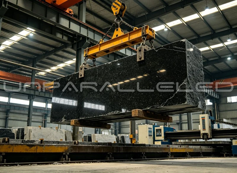
Machine beds made from mineral casting - a resin-bound composite of graded aggregates - are no longer a niche alternative to cast iron. They damp vibration better, they do not need a long natural stabilisation period, and complex features can be formed into the part instead of machined into it. But a mineral casting bed is designed differently from a metal casting, and most avoidable project delays trace back to design conversations that happened too late: an insert placed where the casting cannot flow around it, a channel that crosses a mounting rail, a lifting arrangement nobody specified until the part weighed half a tonne.
This article is a design checklist for buyers and machine builders who are preparing a mineral casting machine bed enquiry. It covers what to confirm with the supplier early, how inserts, interfaces and channels should appear on the drawing, which surfaces are machined and which are not, what information lifting and installation need, how prototype, mould and series stages are reviewed, and how critical mounting faces are verified before shipment.
1. What This Product Actually Is - and Why the Definition Matters
First, a definition, because the market uses the words loosely. The product family discussed here is resin-bound mineral casting: a mixture of selected mineral aggregates and an epoxy resin binder, cast at room temperature into moulds and cured without firing. In English-language literature it is also called epoxy granite or polymer concrete. It is not the same material as UHPC (ultra-high-performance concrete), which is cement-bound, steel-fibre reinforced and processed differently. The two are sometimes lumped together as "mineral casting" in brochures, but their mechanical behaviour, their edge quality, their moisture behaviour and their production process differ, and a design checklist written for one does not transfer automatically to the other. Throughout this article, "mineral casting" means the resin-bound composite - the same terminology used on our product pages and technical documents.
This distinction is not pedantry. The binder governs creep and temperature behaviour; the aggregate grading governs damping and density; the cold-curing process governs which features can be formed and which must be machined. When a quotation says "mineral casting", the buyer is entitled to know which of these systems is actually being offered.
2. What to Confirm With the Supplier Early
The cheapest point in a project to fix a design problem is before the mould exists. Four topics belong in the first technical conversation:
The load map. Static loads from the machine structure, dynamic loads from moving axes, and the locations of the main load introduction points. Mineral casting performs excellently in compression and well in bending at bed scale, but concentrated loads introduced into thin sections deserve a deliberate look at local geometry - usually solved with a local rib, an increased wall, or an insert, and far easier to plan at drawing stage.
The damping requirement. If the bed was chosen for vibration performance, say what it must outperform and in which direction. Damping is a property of the composite itself, but the achieved behaviour of a machine also depends on where the bed is coupled, on what is bolted to it, and on the isolation of the foundation. A supplier who knows the target can comment on section shapes, because damping-to-mass behaviour changes with geometry, not just material.
The interface inventory. List every surface that will touch another component: rails, ball-screw supports, rotary tables, cable chains, coolant trays, covers, nameplates. Each interface is either a machined face, an insert, or an as-cast face with relaxed tolerance - and each choice has cost and lead-time consequences that are visible at drawing stage and invisible after casting.
The environment. Workshop temperature range, coolant exposure, cleaning agents, and whether the bed sees oil. Resin-bound mineral casting tolerates the normal machine-tool environment well, but the enquiry should state the real conditions so the correct surface sealing and edge detail are chosen rather than assumed.
3. How Inserts, Interfaces and Channels Belong on the Drawing
Mineral casting rewards drawings that state intent, not just geometry. The convention that works in practice:
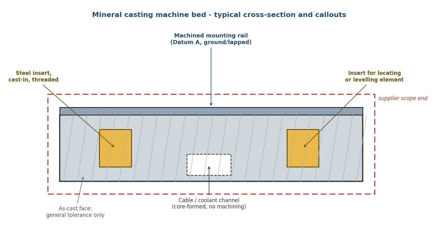
Inserts are drawn in position with their type and function named. Threaded inserts for rail bolting, locating inserts for fixturing, levelling inserts at defined support points, lifting inserts or threaded holes for eye bolts. Position tolerances for inserts are referenced to the datum system, not to as-cast edges. Depth matters as much as position: an insert near a channel wall or near a thin section needs a review before it is frozen, because the casting must flow around it and the local section must carry it.
Machined interfaces are marked as such on the drawing, with the datum system and the tolerances attached to them. The general rule: the few faces that locate the machine's precision components carry tight tolerances and are machined after casting; everything else stays as-cast. A bed with six machined faces and a bed with sixty are different products at different prices, and the drawing is where that difference is decided.
Channels for cables, coolant and hydraulics are drawn as formed features with a route, a cross-section and an entry and exit point. Three checks belong to every channel: it must not cross a machined interface or compromise the section under it; it must be drainable and cleanable; and its openings must land where the assembly actually wants them, which is a question for the machine layout, not for the casting shop alone.
Marking and identification belong on non-functional as-cast faces, agreed in advance, along with the part's orientation marking so that installation crews do not have to work it out from the drawing at two in the morning.
4. Machined Faces Versus Alternative Interface Treatments
Machining is not the only way to make an interface, and on mineral casting it is usually the most expensive one. The decision per interface:
Machine it when the interface needs flatness, parallelism or position accuracy that casting cannot deliver - guide rail seats, spindle carrier faces, datum rails. These faces are milled and often ground after the casting has cured, and their tolerances are achievable and verifiable.
Insert it when the interface is about fastening rather than precision - threads, eyebolt holes, earthing points, locating pins. Cast-in steel inserts avoid machining access and put the thread into a material that carries it well.
Leave as-cast when the face is structural but not functional: covers, cable-chain runs, visible housings. As-cast faces carry general tolerances and a defined surface appearance, and they cost nothing extra.
A useful discipline for the design review: walk the drawing interface by interface and assign each one to one of these three categories explicitly. Interfaces left undecided default to "machine everything", which quietly doubles the machining content - or to "leave as cast", which quietly pushes precision work onto the fitter at installation.
5. Lifting, Handling and Installation: the Information to Reserve Now
Mineral casting beds are heavy and stiff, which makes them safe to handle in one sense and unforgiving in another: unlike steel fabrications, they do not bend back. The design must reserve the information handling needs, early:
Lifting points and their rating. Either cast-in inserts or machined threaded holes for eyebolts, positioned so that the bed lifts level and so that lifting forces enter the section through reinforced geometry. The safe working load and the lifting method belong in the drawing, not in the crew's experience.
Support and levelling concept. Where the bed sits, how it is supported, which points are the levelling elements and what they thread into. The levelling points should coincide with defined support geometry, and the machining of the top rails should be referenced to the datum that levelling establishes.
Assembly order. Which interfaces are used first, which covers and trays go on before the machine is set in place, and which channels need to stay accessible until final routing. A bed whose channels can only be reached after installation is a design defect discovered on the customer's floor.
Transport conditions. Packing, fixing points for transport brackets, and any orientation limits. These cost nothing to specify and are expensive to improvise.
6. Prototype, Mould and Series: What Is Reviewed at Each Stage
Mineral casting has a useful property for project planning: the mould, not the material, is the main tooling investment, so the review sequence can be planned deliberately.
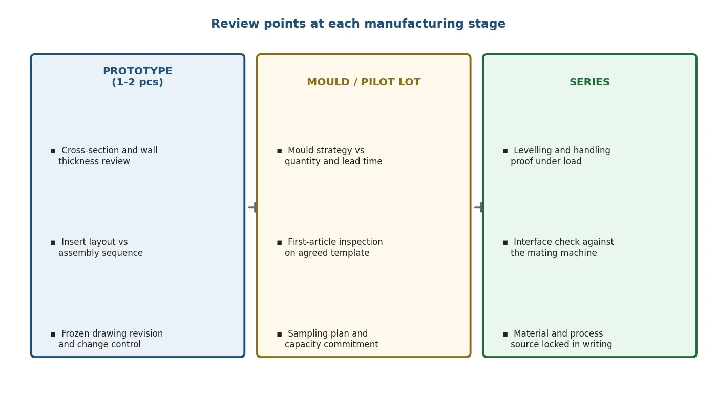
At prototype, the reviews are technical: cross-sections and wall thicknesses, insert layout against the assembly sequence, the machining concept for the critical faces, and the handling concept under real load. A prototype bed should be measured fully on the agreed template and, where possible, trial-fitted into the machine environment, because the finding that matters most - whether the interfaces land where the machine needs them - is cheap to correct now.
At the mould and pilot-lot stage, the reviews shift to process: mould strategy against quantity and lead time, first-article inspection per the agreed template, and a check that the casting process reproduces the prototype's behaviour - density, surface, insert anchorage. It is also the point to agree the change-control rule: no change to mix design, aggregate source or process route without written notice.
At series, the questions are stability questions: the same material system and sources, the agreed sampling plan, stable lead times, and capacity across the programme. A series order should carry forward the prototype's inspection template unchanged, so that every lot is measured the way the first one was.
7. A Case From Practice: One Interface, One Change
A customer came to us with a bed for a measuring machine: a conventional layout with the linear guides on machined rails along both long sides, and the cable channel running between them. The enquiry was complete and the drawing competent. The design review nevertheless flagged a conflict the drawing had not made visible: the cable chain's exit point was directly above one guide rail seat, and servicing the chain would have required lifting the rail and disturbing an alignment that had been ground in.
The change was small and cheap at that stage: the channel was re-routed to exit through the end face instead of the top, the exit opening moved into an as-cast face, and one insert was relocated from the channel wall to a position where the local section was thicker. Casting flow around the insert improved, the rail seats stayed untouched by the channel, and the machine's cable service became possible without touching the alignment. First-article measurement matched the prototype on every critical face. The lesson is the one this article keeps returning to: none of this required advanced engineering - it required someone to walk the interfaces and the assembly sequence together before the mould was made.
8. Verifying Critical Mounting Faces Before Shipment
The final gate is measurement, and it should be agreed as a template, not negotiated per shipment:
Which features are on the report. Every machined interface, every datum, every insert position that locates a precision component. As-cast faces appear as a general-tolerance statement, not as individually measured features.
How each feature is measured, stated on the report. Flatness and parallelism of rails, position of inserts, perpendicularity of end faces - with the instrument and the setup conditions recorded, because the result of a large-area flatness measurement depends on how and where the part was supported.
Which standard the report follows, and what it references. The part, the drawing revision, the equipment, the results, the environmental conditions. This is the same documentation logic we apply to granite bases and other precision components, and it means the receiving inspector can compare the shipment against the drawing revision that was actually frozen - not against a memory of it.
Acceptance criteria for cosmetic defects - chips at edges, surface marks on as-cast faces - agreed with photographs where possible, so that receiving decisions do not depend on who is standing at the dock.
9. The Checklist
Before releasing a mineral casting bed enquiry, confirm: the material system named precisely (resin-bound mineral casting / epoxy granite, not an unspecified "mineral"); the load map and the damping target; the complete interface inventory, each interface assigned to machined, inserted or as-cast; the datum system and tolerances on the machined set; inserts drawn in with type, function, position and depth; channels routed with entries, exits and service access; lifting, support, levelling and transport information reserved on the drawing; the prototype-to-series review plan; and the inspection template with methods and acceptance criteria. Send the drawing with that checklist closed, and the quotation you receive will describe the bed you actually intend to buy.
Our engineering team reviews mineral casting enquiries in this order - interfaces first, sections second, tolerances third - and responds with manufacturability comments before the mould is made. Send us your layout and interface list; the design conversation is most valuable while the drawing is still open to change.
Planning a mineral casting machine bed?
Send your interface list and layout draft - even before the drawing is frozen. We will review insert positions, channel routing and machining scope, and quote with a defined inspection plan. Start the design review →