



A granite base for semiconductor equipment must do more than support machine weight. It can establish the reference for motion, optics, measuring systems, and assembly interfaces-so its material, geometry, mounting features, inspection plan, and installation conditions all matter. This guide helps engineers and sourcing teams define the information needed to select a precision granite base for semiconductor inspection equipment, optical systems, metrology platforms, and precision motion assemblies. Final material selection and performance verification should always be subject to engineering review and the project-specific drawing requirements.
Why Base Stability Matters
Semiconductor and advanced inspection equipment often combine several highly sensitive subsystems in one machine: precision stages, linear motors, encoders, optical heads, cameras, probes, guideways, fixtures, cable-management systems, and environmental controls. The base structure provides the physical reference on which these subsystems are located and aligned.
If the supporting structure experiences unwanted movement, uneven thermal response, poor mounting interfaces, or instability during operation, the effect can propagate through the whole assembly. This may influence alignment, measurement repeatability, image quality, motion settling, or the consistency of an inspection process.
A granite machine base is commonly considered where a system needs a stable, corrosion-resistant, non-metallic structural reference. Granite is widely used in precision applications because of its dimensional stability, inherent vibration-damping behavior, and suitability for accurately finished reference surfaces. These characteristics are relevant to metrology and optical applications, but the actual performance of the complete machine depends on the design, motion profile, support arrangement, environment, and verification method.
For semiconductor equipment, base selection should therefore begin with a system-level question:
What must remain stable, relative to what reference, under what operating conditions?
The answer may be different for an AOI system, a wafer inspection platform, an industrial CT system, a CMM, or a high-speed laser-processing machine. A static metrology frame and a dynamic linear-motor platform can require very different structural solutions.
Typical Equipment Applications
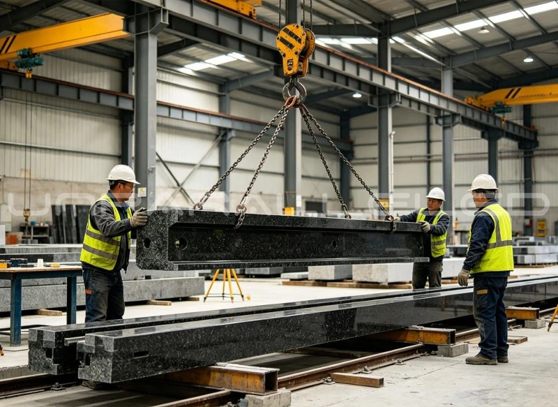
Precision granite components can serve as bases, bridge supports, reference surfaces, gantry structures, optical platforms, guideway supports, or integrated granite assemblies. The equipment architecture and the required inspection or process function determine their role.
Typical applications include:
AOI and optical inspection equipment: Granite may support cameras, optics, lighting systems, fixtures, and precision positioning stages where a stable reference structure is required.
Industrial CT and X-ray systems: The base may support scanning components, workpiece fixtures, motion systems, and measurement references, subject to the complete system's loading and shielding design.
CMM and metrology equipment: A granite structure can provide a stable reference surface or base for probes, guideways, bridge assemblies, and measuring axes.
Laser systems: Precision laser equipment may use granite bases to support optical alignment, workpiece positioning, and motion assemblies.
XY tables and linear motor platforms: A granite assembly may be designed with mounting surfaces, inserts, rail locations, cable passages, or air-bearing interfaces as required by the machine design.
Granite is not automatically the correct material for every semiconductor machine. Equipment that must meet special vacuum, chemical, magnetic, thermal, cleanroom, acceleration, or weight constraints should be evaluated individually. In some cases, a project may use a combination of Precision Granite, Precision Ceramic, Precision Metal, Precision Glass, Mineral Casting, UHPC Precision, Carbon Fiber Precision Beam/Bridge, or Precision 3D Printing components.
UNPARALLELED Group supports this broader range of precision-material solutions under the UNPARALLELED® brand. The appropriate combination remains dependent on drawing requirements, assembly conditions, and project-specific verification.
Engineering Selection Factors
The starting point for a successful granite-base project is a complete drawing review. A quotation based only on overall length, width, and thickness can overlook critical requirements such as insert locations, guideway interfaces, support conditions, inspection criteria, or transportation limitations.
1. Overall dimensions and mass
Provide the finished length, width, thickness, estimated weight, and any limitations imposed by the customer's facility, loading dock, cleanroom route, or installation area.
UNPARALLELED® can support individual-part handling and machining of up to 100 tons, with maximum machining dimensions of up to 20 meters in length, 4,000 mm in width, and 1,000 mm in thickness. These are capability limits, not universal product specifications. Feasibility, process route, lifting plan, inspection method, and delivery arrangement remain subject to engineering review.
For relevant projects, UNPARALLELED® black granite has an approximate density of 3,100 kg/m³. This material value can help with early weight estimation, but final weight depends on actual dimensions, cut-outs, holes, pockets, inserts, and the finished assembly configuration.
2. Static and dynamic loading
The engineering team should understand not only the machine's total weight, but also where forces are applied. Important information can include:
Static loads from frames, fixtures, optical modules, and workpieces
Moving loads from gantries, stages, carriages, cable carriers, and motors
Acceleration and deceleration conditions for dynamic axes
Center of gravity of mounted equipment
Support-point locations and floor-loading limitations
Required stiffness, allowable deflection, and alignment criteria
A base that supports a static inspection fixture may need a different configuration from a granite assembly carrying a fast-moving precision motion platform. The loading model must be considered together with the component geometry and support arrangement.
3. Thermal environment
Even in controlled production areas, temperature gradients can come from motors, drives, lighting, airflow, open doors, operator activity, nearby machinery, or process heat. The customer should define whether the machine will operate in a metrology room, a cleanroom, a general factory area, or another controlled environment.
It is also important to identify which components are mounted on the granite base. Steel rails, aluminum brackets, motors, scales, optical components, and electronic cabinets may respond differently to temperature changes. Their location and heat output can influence the assembly's behavior.
UNPARALLELED Group operates a controlled temperature and humidity workshop area of 10,000 m² for applicable manufacturing, measurement, and assembly work. The production and inspection environment for a specific project should be agreed upon according to the drawing, tolerance requirements, and inspection method.
4. Vibration requirements
Vibration stability is a system issue. Granite can contribute useful mass, stiffness, and damping behavior, but the base should be designed together with its foundation, leveling system, isolation method, moving axes, and surrounding environment.
A project discussion should identify:
External vibration sources near the planned installation location
Internal vibration created by motors, stages, pumps, or other machine subsystems
Required settling behavior after axis movement
Whether pneumatic isolators, active isolation, leveling mounts, or a dedicated foundation will be used
Whether the base is intended to carry air bearings, linear guides, or another motion architecture
Do not define vibration performance from material selection alone. Project-specific verification is recommended where vibration limits are critical to machine operation or measurement quality.
Interface and Assembly Design
A granite base must integrate with the rest of the machine. The drawing should clearly identify functional surfaces and every interface that will be machined, assembled, bonded, or inspected.
Threaded inserts and mounting holes
Threaded inserts can provide mounting points for rails, brackets, covers, sensors, fixtures, or other equipment components. The drawing should define insert type, thread specification, material, depth, quantity, location, and any load or torque requirements.
Through holes, counterbores, dowel holes, tapped inserts, and positioning features should be reviewed as a complete interface system. Hole placement can affect machining access, structural wall thickness, assembly sequence, and measurement requirements.
Rails and motion-system interfaces
If the granite base supports linear rails, air bearings, direct-drive motors, encoder scales, or precision stages, the interfaces should be identified clearly. Important considerations may include:
Rail-seat locations and functional reference surfaces
Straightness, flatness, and parallelism requirements
Fastener pattern, dowel features, and access for assembly tools
Alignment relationships between rails, scale references, and optical axes
Clearance for carriages, cable carriers, limit switches, and service access
These requirements should be treated as engineering specifications, not assumptions. A granite base intended for one rail system may not be suitable for another without design changes.
Cable routing and air-bearing interfaces
Cable routing, vacuum lines, air lines, sensor wiring, and utility passages should be coordinated early. Holes and channels must not interfere with critical reference surfaces, inserts, support locations, or structural features.
For air-bearing applications, the design should specify the relevant interface surfaces, supply connections, mounting arrangement, and assembly responsibilities. The operating performance of an air-bearing system depends on the complete design, including bearing components, air supply quality, surface preparation, alignment, load conditions, and environmental control.
Assembly surfaces and cleanliness
Assembly surfaces should be clearly marked on the drawing. The customer should identify which surfaces require precision finishing, cleaning, protection, or special handling before final assembly.
For semiconductor inspection equipment or clean manufacturing environments, cleanliness requirements may influence packaging, handling, assembly sequence, protective materials, and the final inspection process. Requirements should be stated in the RFQ rather than assumed after production has started.
Inspection and Acceptance Requirements
A precision granite component should be accepted against an agreed technical standard, drawing, and inspection plan. The scope of inspection depends on the function of the part and the customer's stated requirements.
Recommended documents may include:
Approved drawing revision and dimensional requirements
Material identification or material-related documentation, as applicable
Dimensional inspection report
Geometric inspection report for specified flatness, straightness, parallelism, perpendicularity, or hole locations
Insert, threaded-hole, and interface verification records
Measuring-instrument calibration status or traceability information, where required
Visual inspection and packaging inspection records
Delivery, lifting, handling, and installation instructions where applicable
Available inspection equipment at UNPARALLELED® may include Mahr indicators, Mitutoyo instruments, WYLER electronic levels, and Renishaw laser interferometers. The correct inspection method must be selected according to the feature being measured, the component dimensions, the specified tolerance, the inspection environment, and the agreed acceptance criteria.
A measurement report is meaningful only when it identifies what was measured, how it was measured, and against which requirement. For high-precision components, measurement conditions, support arrangement, instrument status, and inspection method should be part of the agreed quality plan.
Engineering Selection Checklist
Before sending a drawing for quotation, prepare the following information:
Latest 2D and, where available, 3D drawing files with revision number
Equipment application and the function of the granite base
Finished dimensions, estimated mass, and expected quantity
Static loads, dynamic loads, acceleration data, and support-point requirements
Required flatness, straightness, parallelism, perpendicularity, and hole-location tolerances
Threaded inserts, through holes, counterbores, dowel holes, rails, and interface details
Motion-system type, including linear rails, air bearings, linear motors, or stage assemblies
Thermal environment, vibration concerns, cleanroom requirements, and operational constraints
Required inspection reports, calibration expectations, packaging method, destination country, and installation limitations
Providing this information early enables a more accurate engineering review and helps identify practical issues before production.
Conclusion
Selecting a granite base for semiconductor equipment is a design and verification process, not a material-only decision. The base must work with the machine's loads, motion system, interfaces, thermal environment, vibration conditions, inspection plan, and delivery route.
A carefully designed granite assembly can support semiconductor inspection equipment, optical systems, industrial CT, X-ray equipment, CMMs, laser platforms, and precision motion systems. However, actual suitability depends on the complete design and must be confirmed according to project-specific requirements.
UNPARALLELED® follows a clear quality policy: "The precision business can never be too demanding." Our customer commitment is equally clear: "No cheating, no concealment, no misleading."
Submit your drawing, technical requirements, inspection expectations, and destination information to UNPARALLELED® for an engineering review. Our team can evaluate the component's size, weight, machining features, assembly interfaces, inspection needs, handling requirements, and practical manufacturing route before production begins.