



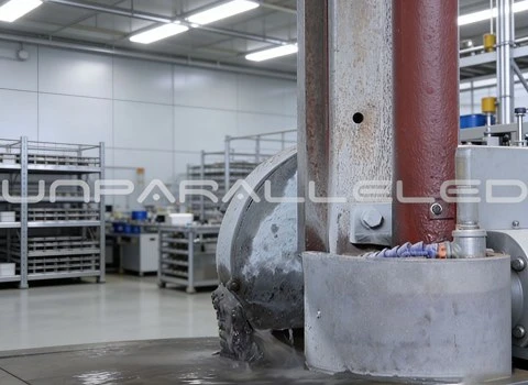
This article is about one specific material system: mineral casting - also called epoxy granite, a mixture of natural granite aggregates bound in epoxy resin, cast into near-net shape and then finish machined on defined surfaces. It is not about fabricated steel bases or solid granite blocks; the design questions differ, and the checklist below follows what must be fixed in the drawing and documents before a mineral casting machine base goes into production.
What must be confirmed before casting
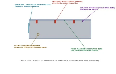
The drawing above marks the five interface groups our project engineers walk through with the customer:
- Threaded inserts - steel sleeves cast into the body. What needs fixing: size (e.g. M8/M12), effective depth, position from datums, and insert material so the sleeve bonds reliably and does not corrode.
- Locating interfaces - pin bores and dowel positions that transfer position to the upper machine structure. They are dimensioned from the same datums the finish machining uses, so that casting-in and post-machining do not stack up errors.
- Guide rail and steel plate mounting faces - these areas carry flatness and position tolerances and must be listed as finish-machining zones with defined allowance.
- Lifting and assembly interfaces - inserts for lifting eyes, levelling pads and transport fixings, placed so handling never loads a machined surface.
- Finish-machining allowance zones - the surfaces milled after casting need enough allowance for flatness to be reached, which the casting geometry has to provide.
The pre-order checklist
Before ordering, the following should be settled on paper: drawing revision and the model file it matches; the complete insert schedule (position, size, depth, material); which surfaces are finish machined and their allowance; the datum system used for both casting and machining; support and clamping during machining; and the acceptance documents - flatness and position report, insert pull or torque checks where required, and appearance standards for the cast surfaces. Sending an assembly drawing rather than only the base drawing usually shortens this step, because interface loads and neighbouring parts become visible.
A project example, from request to verified delivery
An automation equipment manufacturer sent us a base drawing with 46 threaded inserts "as per standard sleeve", without depths or materials, and two guide rail faces toleranced at 0.01 mm flatness over 1,800 mm. In the design review we returned three questions: which inserts carry lifting loads; whether the rail faces could be referenced to the casting datums or needed to be machined in one setup; and the expected clamp positions during machining. The customer confirmed lifting inserts separately, we proposed machining both rail faces and the top surface in a single setup to protect their mutual position, and the insert schedule was completed with depths and stainless sleeves in the wet areas.
The delivered base came with a flatness report for each machined face against the agreed limits, insert position check against the drawing, and photos of the packed part. The customer's incoming inspection confirmed the rail face flatness on their own equipment - the numbers matched because the measurement conditions had been agreed beforehand.
If you compare materials first, our article on what mineral casting is and where epoxy granite bases make sense covers the background; this page is deliberately about the interfaces, not the marketing.
Sending an assembly drawing, your interface requirements and the expected quantity is the fastest way to start: our engineering team will review the casting and machining feasibility, complete the insert schedule with you, and return a proposal with a machining and inspection plan.